
How much power does my submersible well pump use?
Many of our customers and blog readers have been looking for alternative ways to keep their well pump equipment running during power outages. Our blog about sizing generators correctly has been a search engine hit, but we only went over the basics of determining what size pump you have in that article. What if you don’t know what size pump you have to choose the right generator? In this blog we’ll dive in deep to help you discover how many horsepower, how much current/amperage your pump uses and how many watts of power it consumes while running.
Submersible and above ground pumps have a label on them, at least when they are clean and new. This label has information like how many horsepower or kilowatts the motor is rated for, how many amps the motor is expected to use and the voltage that the pump needs to run properly. Finding this label on the above ground pump is usually the work of just a few seconds, but what about the submersible pump? It is often located hundreds of feet in the ground!
Submersible pumps typically have a control box that the wires from the well connect to. This control box will typically have the label on the outside, however some manufactures or pump installers will put detailed information inside. To view inside labeling, you may need a screwdriver to remove the control box cover. It is advised to shut off the power to the pump before removing any electrical covers and practice appropriate electrical safety measures when working with any electrical devices. If your submersible well pump does not use a control box & pressure switch and, instead, uses a variable frequency or constant pressure controller the information, check out our more recent blog specifically addressing the generator size for residential pump systems that use VFD controllers.
If you can’t find the label, don’t get frustrated because there are still a few things you can do to find out how big your pump is, or at least get an idea of how large it is. If you know the contractor that installed the submersible well pump, give them a call! More than likely they will have a copy of the invoice that will show how many horsepower, what size wire, pipe and how deep the pump is. Get this information and hang on to it! These are vital pieces of info when (not if) you need to replace the pump in the future and it will help you determine how much power the pump needs if you are looking for a generator.
If you don’t know who installed the well pump and don’t have any past invoices or records, locate the dedicated circuit breaker for the well pump. Most submersible well pumps are single phase 230 volts and require a 2 pole circuit breaker (2 individual circuit breakers connected together). What amperage rating does the circuit breaker indicate? This chart will help you determine the maximum size pump installed if the installer complied with the national electrical code and Franklin AIM Manual recommendations/specifications on tables 5 & 14. Please keep in mind that these recommendations are for traditional pump equipment that use a control box/pressure switch and large pressure tank.
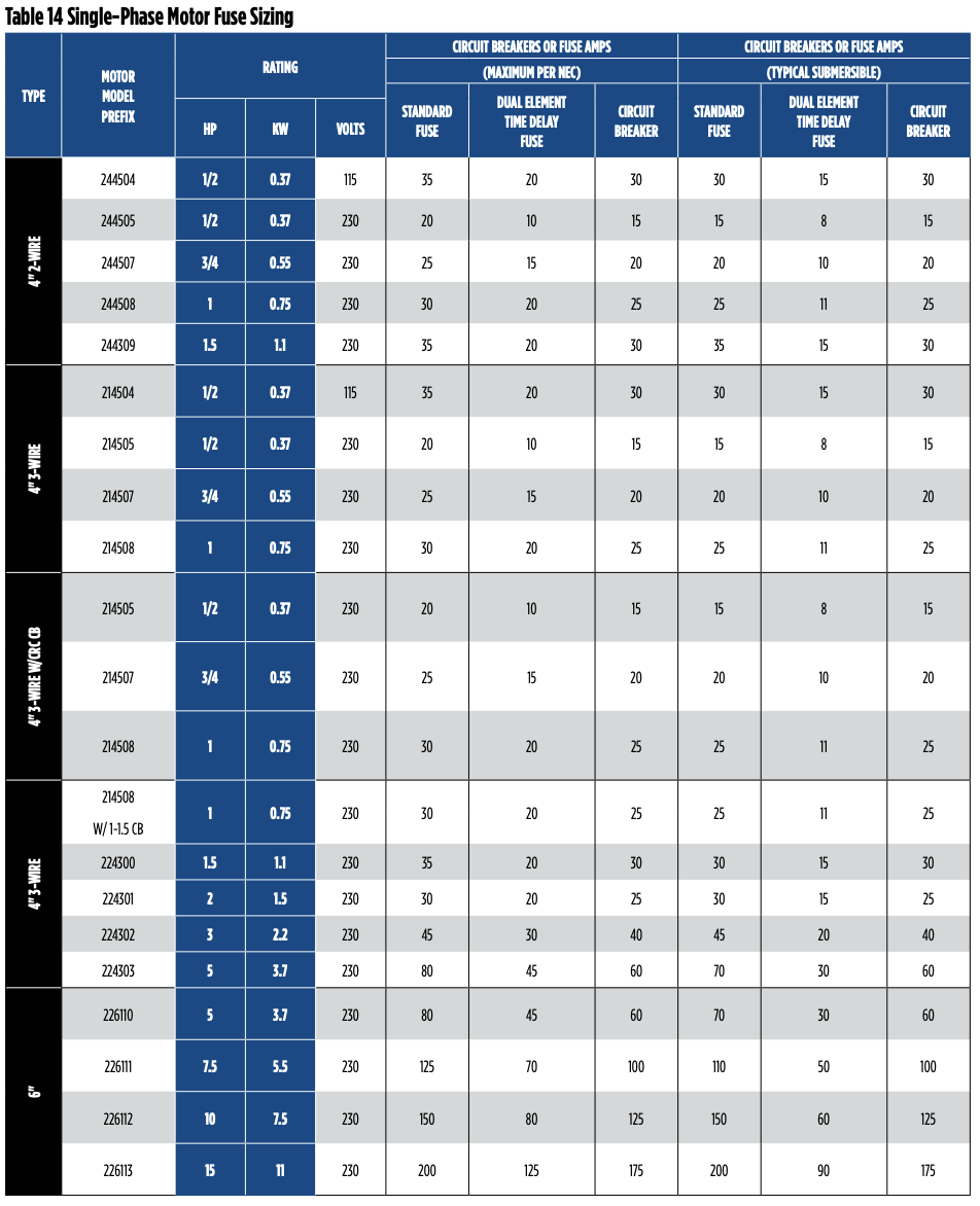
A general summary of circuit breaker sizes and Generator sizes for various 230 volt pumps are as follows:
A 15 amp circuit breaker means the pump is smaller than .5 hp and will use ~5 amps/700 watts during operation and will require at least 1.2 KW internally regulated generator to start/operate the pump.
A 20 amp circuit breaker means the pump is smaller than .75 hp and will use ~8 amps/1100 watts during operation and require a 2 KW internally regulated generator to start and operate the pump. (1 HP pumps are sometimes run on a 20 amp breaker depending on the installer and wire size available)
A 25 amp circuit breaker means the pump is 1 HP or smaller and will use ~9 amps/1400 watts during operation. A 1 HP submersible well pump will require a 2.5 KW internally regulated generator to operate the pump.
A 30 amp breaker means the pump is smaller than 2 hp will use ~13 amps/2300 watts during operation and will require a 4 KW internally regulated generator to operate the pump. (This size breaker is also used for 1.5 HP pumps which require a 3 KW internally regulated generator for proper pump operation.)
A 40 amp breaker means the pump is smaller than 3 hp will use ~16 amps/3200 watts during operation and require a 5 KW internally regulated generator for proper pump operation.
A 50 amp breaker means the pump is smaller than 5 hp and will use ~25amps/5300 watts during operation and require a 7.5 KW internally regulated generator for proper pump operation.
Did you NOTICE that the circuit breaker is significantly larger than the amount of current/amperage the pump uses during operation? This is not a typo or mistake! The circuit breaker needs to be significantly larger because the amount of current/power used to start the pump spinning/pumping is very high. Once the pump has finished accelerating to speed, the current and power usage will drop down to the normal range. For this same reason you need to size the generator for the starting current (circuit breaker size) and not the running current of the pump! Check out more information on page 5 of the AIM Manual or check out our blog if you want more info about sizing a generator for your submersible well pump.
If you are exceptionally astute, you will notice that a 1 HP pump uses 1400 watts and you’ll scratch your head trying to make this jive with the 746 watts that your high school physics class taught you is equivalent to 1 HP. Why the difference? Pumps are rated by the usable work that they perform after all the electrical and mechanical inefficiencies have been lost. The pump may produce 1 HP/746 watts of usable water flow/pressure, but the actual amount of power required to do this is a bit higher due to the inefficiencies. Selecting the correct pump for your well can help maximize efficiency AND decrease the capital expenditure for replacement equipment - check out our blog on this topic to learn about how to choose the most efficient pump for your application, it can save you money up front and in the long run!
Now, let’s say you can’t locate the circuit breaker for your pump and you haven’t been able to find the label/it is illegible and you don’t have any records about the pump. What to do? If this is your situation you may want to call a professional and have them come take some basic electrical measurements including winding resistance and actual pump run current (amperage). This will give you a very good idea what size pump is in the well and how much power it uses. A professional in our area is going to charge ~$200 to travel to your house, take the readings and perform a few more checks on your pressure tank and pressure switch then give you an idea of what is going on and make suggestions about anything unusual.
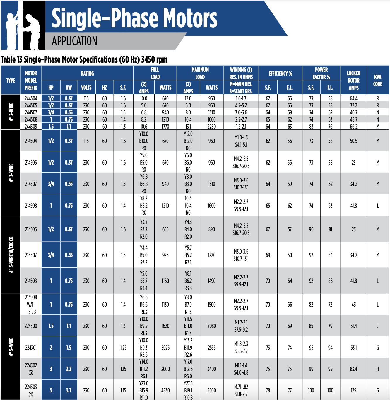
If you are handy and have knowledge and training tow work safely with electricity and electrical components, this is something that you can do yourself with a few pointers. Invest the money you would have spent on a service call into a decent multimeter like the Fluke T6-600. Next, shut off the power to your pump and pull up the reference charts from Table 13 of the Franklin AIM Manual (also shown at the bottom of this blog) Now, locate the power cable to the submersible well pump, it should have 4 colored wires: Red, Yellow, Black and Green. Switch the T6-600 to the “A” setting and then slide the yellow forks at the top of the meter over the yellow wire. Keeping your hands clear of all electrical equipment and wires turn on the power! Now run some water until the pump turns on and take note of the amperage reading and compare it to the Table 13! If you have only three wires going to your submersible well pump and there is no control box, then just measure the amperage on either of the non-green wires and compare the reading to the appropriate chart in the Franklin Manual for 2 wire motors (not very common). Ensure that you turn the power off and reinstall any electrical covers, then turn the power back on when you’re finished.
If you want to double check and you have a 4 wire motor, shut the power off to the well pump, disconnect the yellow, black and red wires from where they are connected, switch the T6-600 to the Omega sign (for resistance readings in ohms) and touch the red/black tester leads to the black and yellow wires that lead to the pump and write the number down. This is the main winding resistance (M). Now touch the red/black tester leads to the red and yellow wires that lead to the pump and write the number down. This is the start winding resistance (S). Compare these resistance readings to the readings found in Table 13 of the Franklin AIM Manual and then carefully reconnect the wires the way you found them and turn power back on to the pump equipment. You should have a very precise idea of what size pump is in your well. Write the information down and keep it in a handy place! Make sure you put the wires back where you found them and turn the power back on or you won’t have any water. Refer to figure 11 in the Franklin AIM manual for additional instructions on this procedure.
Our professional team at Oakville Pump Service helps our clients from Napa, Calistoga, Pope Valley and everywhere in between as they keep the water flowing to businesses, homes and agriculture. Give us a call today (707) 944-2471 if we can help solve your water related problems!